Very small things can cause very big problems (just consider the manflu virus).
It’s not all about the large, easily visible features – as you’ll see.
We recently undertook a trial to inspect metal laminates for a company that makes engine parts (mostly bearings). The components we looked at were copper/steel bimetallic strips.
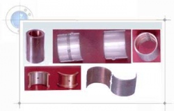 The metal laminate strips in question are used for shell bearings, big ends in engines, driveshaft bearings and similar – so they need to be exactly right!
The task
The prospective client asked Bytronic to trial a set-up to measure the steel/copper thickness. We aimed for a 5mm FOV (field of view), ran some tests, and produced a report showing the achievable accuracy with 1280×1024, 800×600 and 640×480 mono camera.
We took repeated images using the three different resolutions, and then collated the strip measurements into a report that indicates accuracy, consistency, and standard deviation.
The images below show the types of variation we were looking for (and found, in this case):
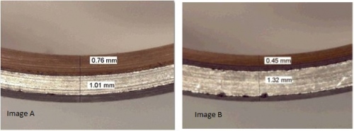
In image A, the top (copper) strip is much thicker than that in image B, while the bottom (steel) strip is considerably thinner than its counterpart in the second image.
In an ongoing drive for quality and consistency, the manufacturer wished to verify that the thicknesses of the two metals were within the design spec.
The consequences of inconsistency can be enormous: bearing failure in an engine could lead to engine failure, a product recall, and all the expense that entails.
Achievable accuracy
The level of accuracy we are able to achieve depends on lighting, the clarity of edges, blur factor, focal distance – and all manner of other variables.
Measurements taken with our technology are accurate to between one-tenth of a pixel (under perfect conditions and with an optimistic outlook) and around half a pixel (which is fairly pessimistic in a real-world environment).
If the spec required 0.1mm accuracy, we’d be pretty confident that we could achieve that. However, there is always a payoff: the higher the camera resolution, the more accurate the measurements – but the more expensive it is. Plus, higher res often means a longer processing time. We can get around this by using cameras with faster processors, but that adds to the price further.
It’s all a matter of finding the best solution for the client, taking into account their requirements, budget and deadlines.
Camera set-up
We tried two cameras out, and this is what we found:
Cognex 5100
- 25mm lens
- 20mm extension tube
- FOV = 4.2mm (measured using calliper)
- DFL (dark-field light)
With this set-up, we were unable to measure to a precision of 0.01mm at an FOV of 4mm. So we decided to try the extra resolution of the 7402 camera.
Cognex 7402
- Macro lens
- End of lens to metal strip = 32mm
- 20mm extension tube
- FOV = approximately 5mm (scale calibrated using chart)
- Bar light angled facing the edge of the metal strip
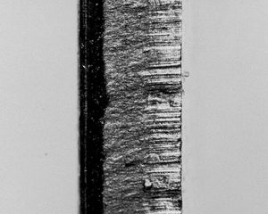
We had to calibrate the camera manually because the software could not pick up the blur-edged squares. (No fault of the camera: printers cannot print calibration grids accurately enough at such small sizes.) The images below show our typical results: the steel edge (bottom edge) was easier to work with, but the copper edge shows the cut lines. This caused problems when trying to accurately detect the edges.
Overcoming problems
Working with such small objects presents a number of challenges, not least of which was the lighting. In order to differentiate between the copper and steel and highlight the boundary, we had to test a number of lighting types and positions.
Ultimately, we settled on a bar light angled to face the edge of the metal strip. This meant that we ended up inspecting the surface finish of the edge, which was the grain structure of the metal itself.
We noted that the depth of the metal strip tapered off towards the edge, so the centre of each strip is slightly thicker than the edges – this needed to be taken into account.
The boundary between the copper and steel has quite a large overlap, which led to the question: where should we measure from?
We also had to contend with the environment as a whole: we were looking closely at small-scale items in a heavy industrial environment. As well as tough lighting requirements, we also had to contend with dust, muck and variable products. Not an easy task, but we managed it!
The overriding problem was a factor of the machinery itself: the strip position was unstable, so we were unable to keep the strips within the narrow FOV. However, if the client can solve their machine stability problem, we’ll be able to ensure their bimetallic strips are consistent… watch this space!